Why Does My Marantz 250 Amp Keep Eating the Protection Relay?

Davidmac5

AK Subscriber
Subscriber
Hi all,

I have a 250 amp that I have done an extensive restoration on both channels to include all new hFE matched pre-driver, driver and output transistors, matching differential pair, all new capacitors throughout, new bias resistors. I had the idling current set at 13mV on both channels and it was stable I also had zero volts set on the DC offset. It played perfect for about 5 hours and then all of a sudden the left channel went out and protection relay went up in smoke. The relay contacts had welded themselves to the contacts that are not used, when I first purchased this amp and started working on it I found the same thing the relay was toast and the contacts had also welded themselves to the unused contacts. I don't see any other damage to either board or any burnt or damaged components.

I plan to tear into it this weekend and start checking things out, but why in the heck would the relay keep going up in smoke after a few hours of use and the contacts welding themselves to the two contacts that are not even used or connected to anything? Like I said I don't see any other damage anywhere except an extra crispy protection relay. Any thoughts or ideas would be greatly appreciated.
 
I found an Original NOS relay on the bay and installed it and it worked for about 5 hours total time before it shorted out. I do have a MY2-02-24 that I internally rewired and had planned to use before I stumbled across the NOS one, so I will be installing it next but wanted to make sure that there isn't something else that I should look at that might be causing the relays to go up in smoke. I was hoping some tech's like you who are smarter than I am could point me in the right direction.
 
The amplifier is working normally, the NO contacts are closed, then the sound cuts outs and the NC contacts are welded together? Sounds like the relay is de-energzing, protection circuit, then welding the NC contacts. How else would the NC contacts get welded if the relay is energized? But then again if the NC contacts are not connected to anything there should be no current drawn to do the welding. Weird. It's a DPDT relay? Are the unused pins cut off?

Craig
 
Last edited:
The amplifier is working normally, the NO contacts are closed, then the sound cuts outs and the NC contacts are welded together? Sounds like the relay is de-energzing, protection citcuit, then welding the NC contacts. How else would the NC contacts get welded if the relay is energized? But then again if the NC contacts are not connected to anything there should be no current drawn to do the welding. Weird. It's a DPDT relay? Are the unused pins cut off?

Craig
Yeah, agree, was thinking how do the NC contacts get welded unless they are connected to something? Are they grounded on this model. Too lazy to go look at the schem!
BTW - love the avatar photo of my favorite fighter/bomber jet. I grew up next to a NAS and saw these all the time as a kid during the early days of the Vietnam War.
 
I would say that's the wrong relay if the coil is on the end pins. Pins 9 and 12 are the Common pins, 1 and 4 NC, 5 and 8 are NO. That's the way you swapped the pins OR that's the way you are going to swap the pins? It says the coil has polarity, is the polarity correct? I re-read your post, you already rewired it.


That's a picture of #7463, Capt. Ritchey's jet, the only "official" AF Ace of the Vietnam War. I got to work on it while at Kadena AB, Okinawa back in the 70s.
 
A relay with coil on the end pins hasn't been found yet and may not exist is why the MY ones get rewired internally. I've done a number of them, and it works fine.
 
The relay I installed was the correct one, like I said it worked just fine then after a few hours of use it fried itself. I have a rewired MY relay ready to install to replace the one that just burned up. So it's not a matter of if the relay is the correct one but more of a question of what is causing it meltdown after a few hours of use with no other apparent damage to the amp? I would hate to install another relay only to have it do the same thing, finding what caused it in the first place is my biggest concern.
 
The relay contacts had welded themselves to the contacts that are not used, when I first purchased this amp and started working on it I found the same thing the relay was toast and the contacts had also welded themselves to the unused contacts.
  1. If the relay was installed correctly on the board and the N.O. relay pins are NOT connected to anything (see board layout), there is NO WAY that I can think of that they would be fused to the fulcrum contacts.
  2. Also, when the relay is energized, high current flows through the relay contacts from the power amp output (see next bullet for current).
  3. e.g. 125W (per channel) = V^2/8Ohms, V = SQRT(P x R) = SQRT(125 x 8) = 31.6V, so at max power output voltage at the 8 ohm speaker should be 31.6v.
  4. The current through the relay contacts is given by: I = V/R, I = 31.6v / 8 Ohms = 3.95A through the relay contacts. MY2 are 5A contacts, so that should be OK.
  5. What is the contact rating for your replacement relay?? Are the contacts gold or silver?
  6. You should be able to measure the voltage across an 8Ohm wire-wound load resistor.
  7. Measure the coil voltage to make sure that it is 24VDC and not much more (MY2 is 110% of rated voltage, 24v x 110% = 26.4v). if your voltage is much higher you could be generating excess heat through the coil. What is your relay voltage across the coil? Also, check for excess AC voltage across the coil, maybe a defective rectifier diode.
  8. Or, C303 filter cap is bad passing more AC to relay coil?
 
Last edited:
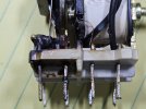
Here are a couple of photos of the relay removed. As can be seen the contact for the right channel speaker has welded itself to the contact with absolutely no connection to anything and the other photo shows the left channel contact in good condition with no issues. The other relay that I removed when I first got the amp had done the same exact thing on the same side.
 

Attachments

  • r-1.jpg
    r-1.jpg
    101.2 KB · Views: 38
  • r-3.jpg
    r-3.jpg
    165.1 KB · Views: 38
...then all of a sudden the left channel went out and protection relay went up in smoke.
@Davidmac5, I'm confused by your photos and description in the first post.
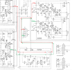
If I trace through the schematic and relay board layouts, the burnt side of the relay corresponds to the RIGHT channel output, not Left???

Here is what I did (please follow this and see if I made an error):
1711849558706.png
The burnt pins are connected to pins 5 & 6 of the PCB (Green trace) according to the SM board layout. Pins 7 & 8 connect the Red channel.
1711849588652.png
If you follow the green arrows, they are connected to the Right channel speakers and the bottom amp board.
So, either there is an error in the schematic, or it is the Right channel that has a problem, not Left.
1711849622988.png
According to this schematic R302 is connected to the L channel (the Red line) which matches the schematic.
1711850088533.png
 
my theory here i think is plausible . ok here goes . the relay isnt holding the contacts together with the correct force . not enough current or possibly ac current leaking .
so best check voltages ac and dc right across the relay coil when out of protect . at least rules it out if i am wrong .
 
Your diagrams are correct, I went back and reread my initial post and I misspoke I meant the right channel not the left, sorry about that. I checked the right channel board and there is no damage to any of the components and all transistors test good and still have the same hFE reading as they did when I first installed them. But something is causing the right channel contact to burn up but not right away and this is the second relay to do that in the exact same way.
 
the relay isnt holding the contacts together with the correct force
Maybe the relay contact on the bad channel has too much resistance because of carbon deposits or not enough pressure due to your theory of insufficient current/voltage. This could cause arcing between the two contacts that would heat up the silver pads until it finally lets go and with the pad so hot, it actually "welds" itself to the un-connected pad.
 
Maybe the relay contact on the bad channel has too much resistance because of carbon deposits or not enough pressure due to your theory of insufficient current/voltage. This could cause arcing between the two contacts that would heat up the silver pads until it finally lets go and with the pad so hot, it actually "welds" itself to the un-connected pad.
ah . just seen this in the original post .... I found the same thing the relay was toast and the contacts had also welded themselves to the unused contacts . the word unused is now making me wonder .
pictures might help here
 
I have a MY2 rewired and ready to install, Will need to do that to check the voltages on the coil?
 
Back
Top Bottom